 |
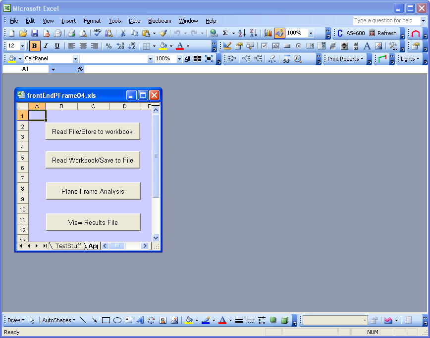
| frontEndPFrame04.xls |
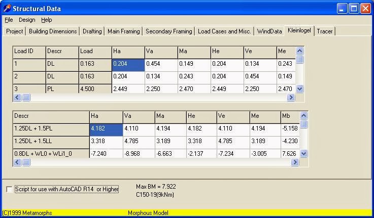
In this way existing data files (.dat) can be opened and edited in Excel. Since reading a file into a workbook over writes the contents of the cells, its not a good idea to calculate the geometry or required loading in the worksheet cells, it is better to generate the model using vba which is the point of the exercise. Using the variables and data structures now defined can write vba code to build a model directly into those variables and by pass the worksheet. The worksheet was just used to verify can read and generate the file through the use of the variables. The file format of the output doesn't match the file read, as the original data files were generated by QPro. Once I had got QPro to generate data files which pframe could read, I didn't worry too much that the file didn't match the exact format of the files saved by pframe. When converted to Excel the format for numbers was taken from the format assigned to the Excel cells, this is no longer done, the format is now hard coded into the vba code. This was done because the file read macro first clears the cells, whilst this has been modified to only clear the contents, the macro can read data files larger than the maximum formatted data area (highlighted in yellow in worksheets) and therefore some format will need assigning to these extra records. The hard coded formats also closely match the original Pascal formats: not liking some of the original formats I have changed them with out affecting the ability of the original application to read the data (thus far).
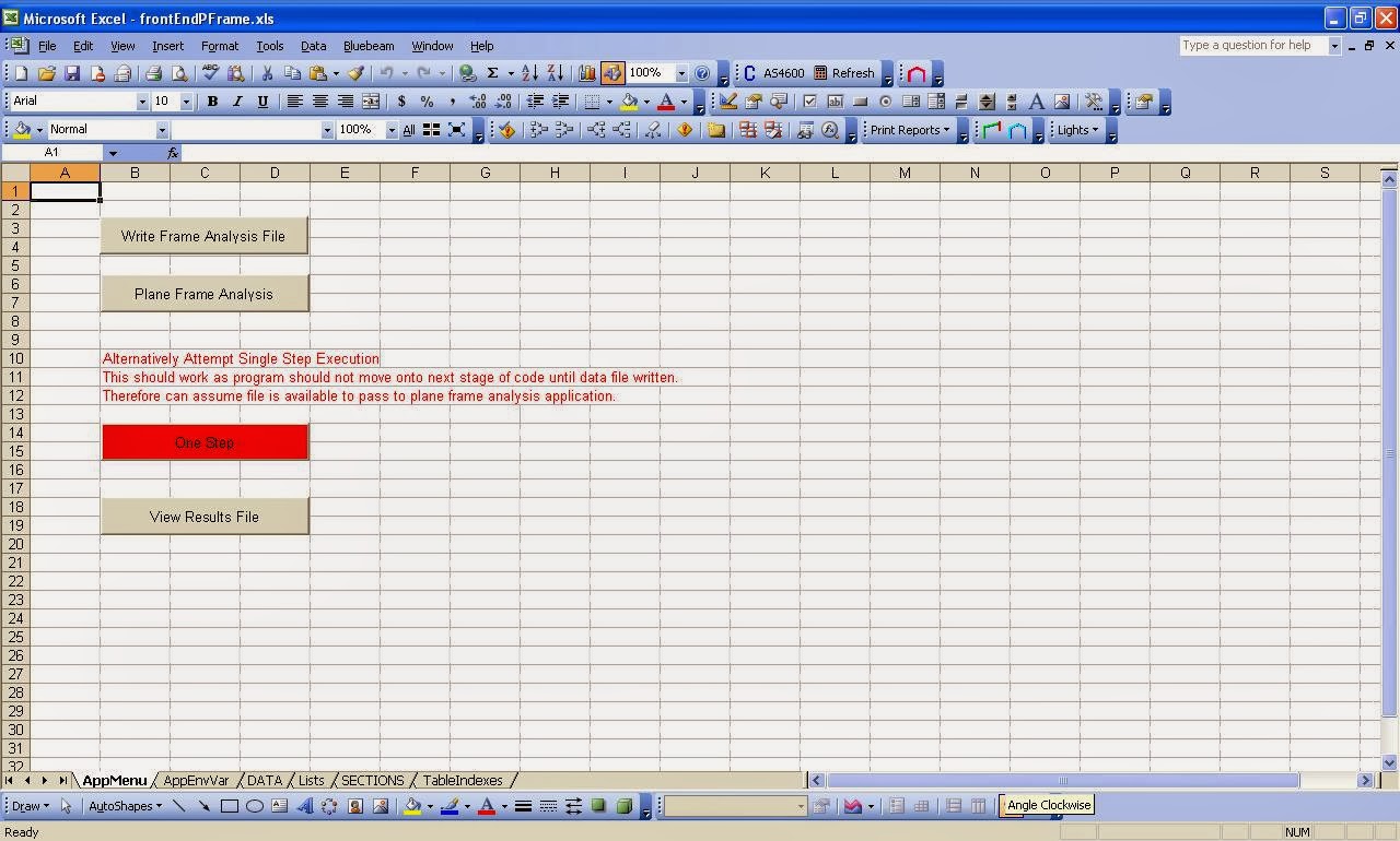
From this point forward will need to move away from buttons in the worksheet. As far as I know, vba variables have a life as long as the execution of the macro. Thus when macro stops, the variables cease to be accessible, though the memory may not be cleared. This is the reason for storing the contents of the variables to the worksheet, and then reading back from the worksheet. Though I did read recently that global variables do retain values between vba calls: maybe. Before including the subroutines for reading the data into the variables I did trial reading then writing without storing and retrieving from the worksheet first: the two buttons seemed to work. However I put that down to valid data still being in memory, and same chunk of memory being addressed when macro next macro run, in other circumstances the data may not be valid and may address different chunk of available memory. This is based on past experience with Excel 97, though at that time I admit not overly familiar with use of the Public keyword, so past failures to initialise variables via open workbook method may have been because of not having global variables: though that seems it would have complained about unknown variables and the initialisation wouldn't have worked. Not something I really want to test or rely on: so will assume that from one vba call to the next all variables are wiped. Besides, since making the test for this application, I have removed the global variables and made local to the main class.
So on the assumption that variables are wiped from one vba call to the next it is necessary to keep the vba code active, and to do that need to move buttons from worksheet to a vba form: and have the form retain control until all tasks complete. The alternative is to repeat large segments of initialisation code on each vba call. This latter approach was adopted for the wind loading functions contained in schTechLIB, each function calls subroutines which load arrays which are then searched for data: may have to revisit that and see if I can initialise once.
Another problem to be addressed is access to the variables external to the class in which they are defined. The variables are arrays and vba does not allow public arrays in the definition of a class. So whilst converting records into classes in Turbo Pascal and Delphi is relatively easy its cumbersome in vba. An alternative is to use collections in vba, these can be public, however these are highly likely to be incompatible with the analysis routines of plane frame. {Noting that idea is to incorporate plane frame in the code not shell out and pass data file to a console application. The console application is just a development tool, and not affected by any code I write for the front-end creating the model to be passed to the frame analysis. The first task is to auto-generate a valid structural model of a manufactured structural product (MSP): not analyse it, that task comes later.}
If don't use collections then need to write property (Let, Get, Set) methods to access the individual elements of the arrays. At present only written one of the classes in Pascal, vb.net and vba, and use of collections keeps vba most similar to Pascal and vb.net.
So as to which is the better option I will work out as I attempt to gain access to the variables and define a structural model.
Structural Design
At the moment I assuming that structural design is split into three stages:
Stage1
Consists of creating the structural model:
- Dimension and Geometry
- Design Actions
Stage 2
Consists of Analysing the structure and determining the reactions and action-effects. The analysis used depends on the analysis used. The tools used for the analysis depends on the complexity of the analysis.
Stage 3
Consists of:
- Component sizing
- Connection Design
- Footing Design
However the whole process is not all that simple, as connections and footings themselves have their own components and may require repeating stage 1 to stage 3, using different analysis methods suited to the details of the component considered. That is steps 2 and 3 of stage 3 can be removed and these components considered as requiring their own structural models. {eg. connections modelled in isolation along with applied forces, using finite element method}
So cpframe only covers stage 2 for structures which can be modelled as plane frames. The front-end for cpframe covers stage 1, and the back-end covers stage 3. There is plenty of software available for stage 2 and stage 3: though not much choice for software covering Australian materials codes. It is stage 1 however where the problem lies with respect to rapid design of manufactured structural products (MSP). For simple MSP's a few simple calculations in a a spreadsheet will suffice for all stages, for more complex structures some analysis engine is required for stage 2. If using an analysis engine then a structural model needs to be built from simple user input. For structural frameworks the form of the structural model is relatively similar, for example I only need to add a few extra fields, add WriteArc methods to all the classes to export the model to a MicroStran .arc file. These methods I already have in classes specifically written for writing MicroStran files. {Pity I think MicroStran even needs to import the arc file. Otherwise could launch that instead of cpframe.}
So given that the data structures required to represent a structural model are relatively similar I can create my own data structures and use to create models for export to what ever structural software I choose. Note not concerned with picking up the dimension and geometry from a CAD model and adding loads to it: the dimension and geometry are to be auto-generated from a few simple parameters and no other variations permitted. If want other variations then export a model for import into general purpose structural analysis software. An MSP has a defined structural form and a limited set of parameters: if the structural form changes then it is no longer the off-the-shelf MSP. I don't see the purpose of software to permit design at point-of-sale (PoS) but to constrain the options available so that the customer knows they have just defeated the entire point and purpose of going to a supplier of MSP's: and consequently some significant period of design and engineering is not required. On the other hand want to make more customisable options available at the PoS. So that eventually get auto-generation of basic options and then manually edit more custom options: with the allowable editing constrained. {NB: Some advanced level CAD systems for more than 20 years now, have been able to define dimensions by mathematical expressions. For example the span can be set to twice the height. Plus various nodes or points can be used as constraints and references. However that doesn't necessarily equate to being able to increase quantity of components, such as varying the number of portal frames with the length of the building. Also in the building industry they don't pay to much attention to assemblies and sub-assemblies: so the building rather than being a series of portal frames becomes a forest of columns with a collection of rafters. Thus 3D modelling can change the perception of the structure: getting away from the sub-assemblies which make it up.}
Any case the focus at the moment is auto-generation of the structural model, and ultimately being able to analyse that model using various tools to get comparative checks on structural adequacy, so that independent technical checking is viable. In the past and even now, independent checking is a problem, the manufacturers use propriety software generate and check compliance in a few minutes and the city councils engineer certifying the structure may require a week to check the design using general purpose tools: or otherwise simply reading through the reports produced.
So my view is to provide the tools to the certifiers and general designers first for use with general purpose structural analysis tools. This in turn increases the potential for MSP's in the first place, and with MSP's comes the manufacturers desire to limit what the sales team can sell to keep the production economical. So go from the flexible to more and more constraints.
Download frontEndPFrame04.xls .
DISCLAIMER :
Users of the software must accept this disclaimer of warranty :
The software is supplied as is. The author disclaims all warranties, expressed or implied, including without limitation, the warranties of merchantability and of fitness for any purpose. The author assumes no liability for damages, direct or consequential, which may result from the use of the software.
Revisions:
[13/02/2014] Original
[23/04/2016] Changed download links to MiScion Pty Ltd Web Store